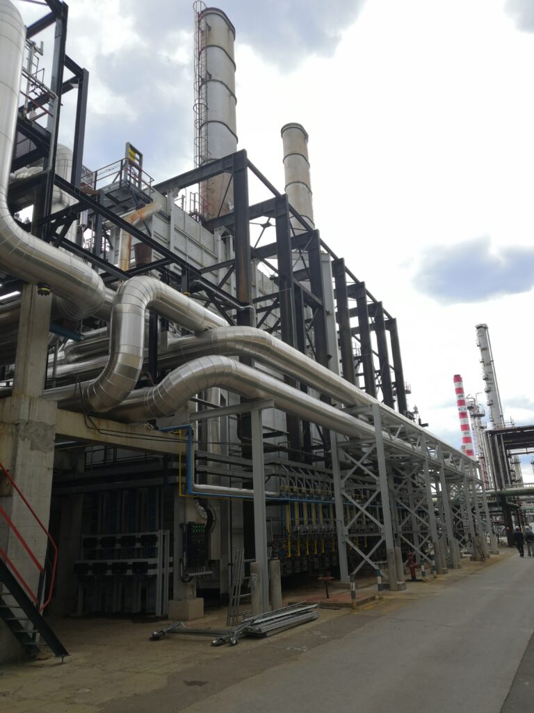
1) Project overview:
Industry: Oil & Gas
System: Process Furnace (catalytic reforming)
Scope: Instrumentation + Control System Design + Site Support
This project covered the full control and instrumentation scope for a fired heater serving a catalytic reforming (platforming) unit. The solution provides safe start-up and shutdown sequences, stable temperature control, burner and fuel-gas management, and an integrated emergency shutdown system, designed in accordance with applicable industrial safety standards.
2) Process & control objective
The furnace had to:
- Maintain stable outlet temperature
- Control fuel and air ratio
- Monitor flame and combustion
- Protect the unit against unsafe conditions
- Interface with the plant control system (DCS), Emergency shut-down system (ESD) and burning management system (BMS).
3) System architecture (P&ID)
- Field instruments (temperature, pressure, flow, flame detection)
- Valves (shut-off valves, control valves with positioner)
- DCS-based control system
- Emergency shut-down system (ESD)
- Burner management system (BMS)
- Operator SCADA
- Safety interlocks and alarms
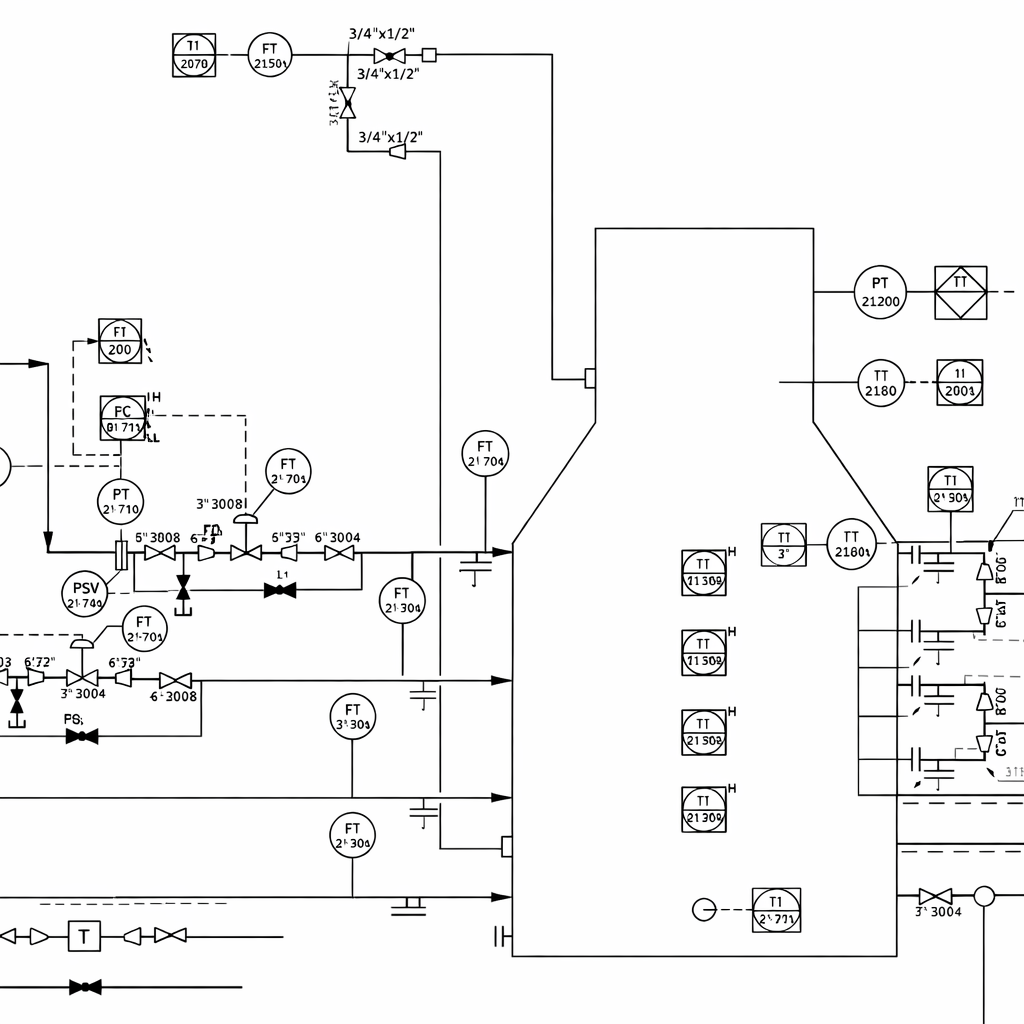
4) Instrumentation scope
Key instruments designed and specified:
- Temperature, pressure, flow, level transmitters
- Gas analyzers
- Flame detectors
- Valves (Control, shut-off valves and pressure safety valves)
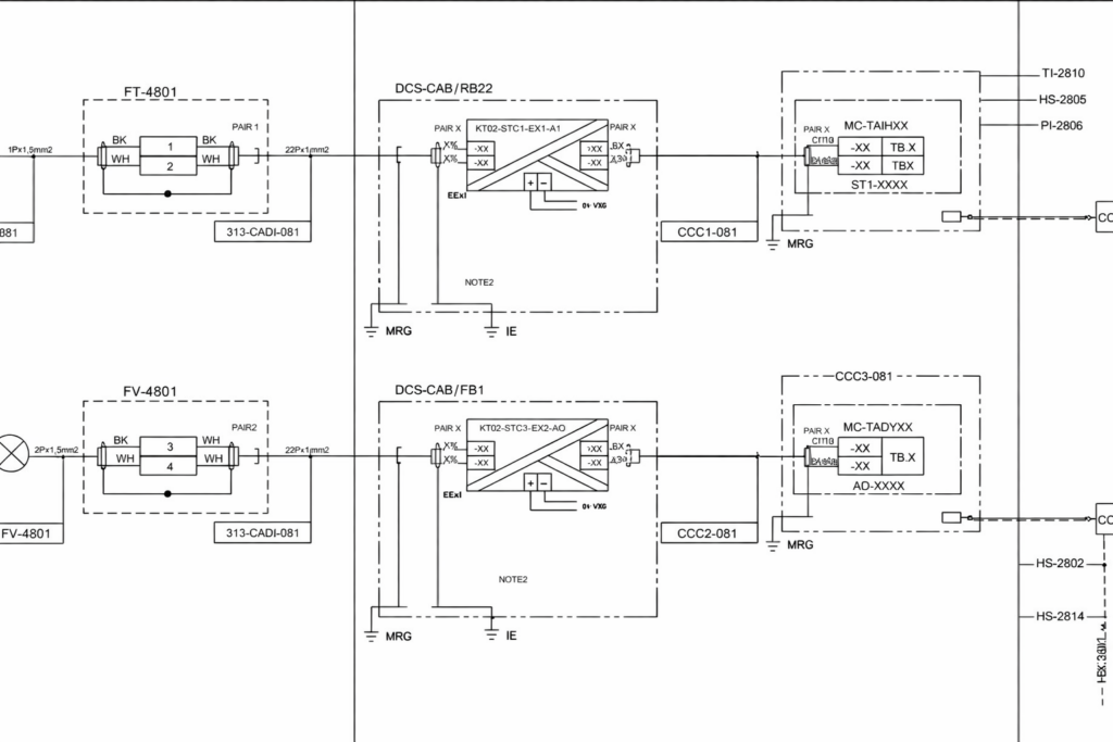
5) Control philosophy
The furnace was controlled using a layered strategy:
- Temperature control loop regulating firing rate
- Fuel-to-air ratio control for combustion stability
- Start-up and shutdown sequencing
- Trip and interlock logic to prevent unsafe operation
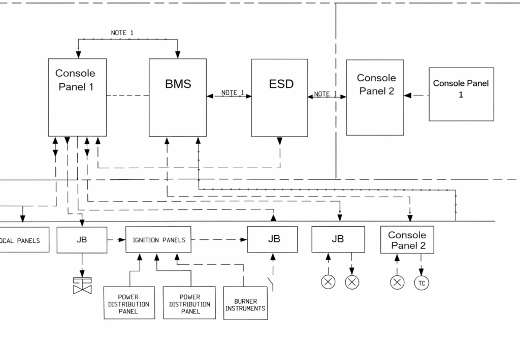
6) Engineering documents produce
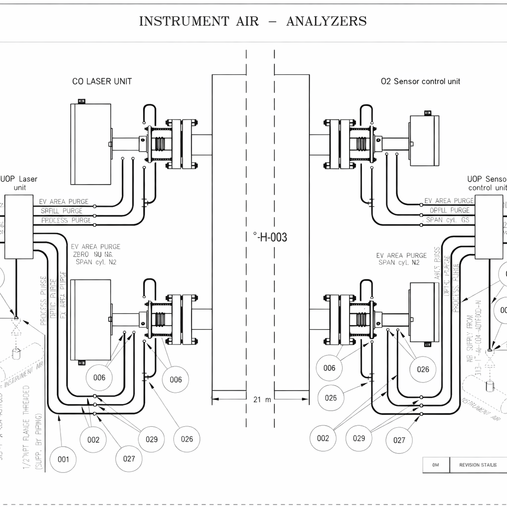
- P&ID
- Loop diagrams
- Instrument datasheets
- Instrument index
- I/O list
- Control philosophy
- Interconnection diagrams
- Junction box wiring
- Hook-up drawing
- Cable data sheet and cable list
- Cause&Effect chart
- Site commissioning and test sheets

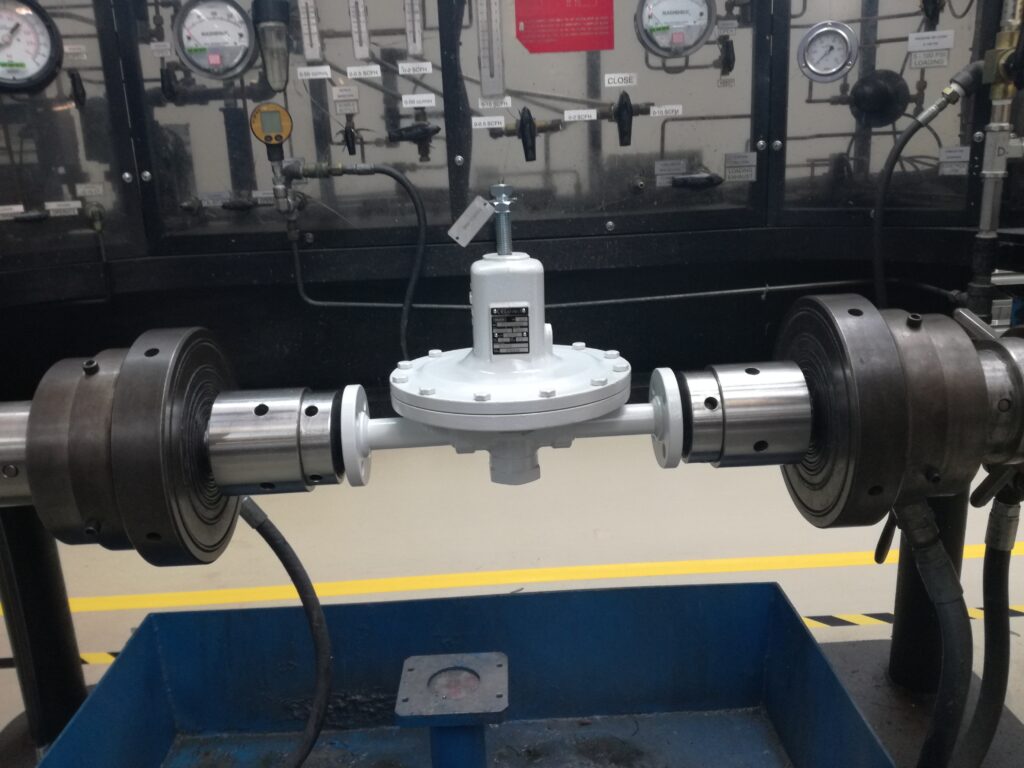
7) Factory acceptance test (FAT)
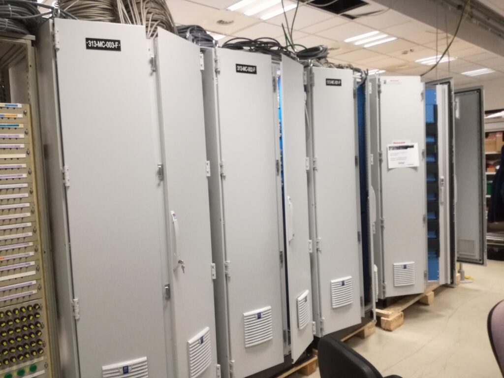
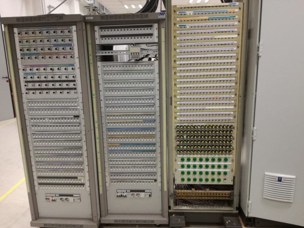
A Factory Acceptance Test (FAT) was performed to verify the complete functionality of the furnace control package prior to site installation, covering the control system, field devices, and local interfaces.
- Control system functionality (logic, sequences, alarms, interlocks)
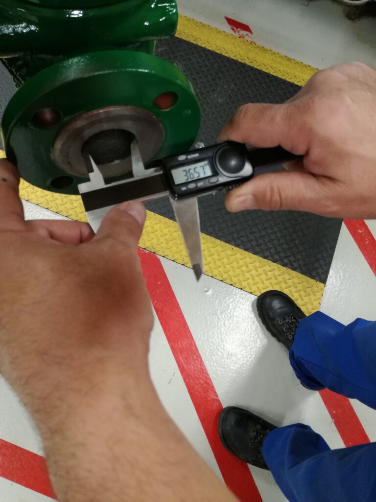
- Control valve functional checks (actuation, positioning response, fail action)
- Shut-off valve verification (open/close command, feedback, fail-safe behavior)
- Local panel checks (wiring, indications, selector switches, local commands)
- I/O verification and signal simulation where applicable
8) On-site engineering
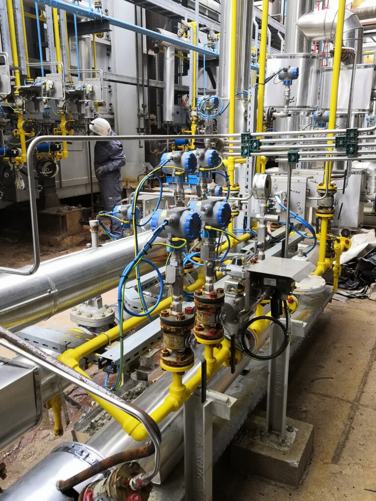
On-site activities included:
- Instrument installation verification
- Loop checking
- DCS,ESD,BMS I/O testing
- Support during commissioning
- Troubleshooting signal and control issues
9) Result
The furnace control system was successfully implemented and prepared for safe operation, with all safety, control, and monitoring functions validated during commissioning.